Hello, Everyone
For the past few years, I have been successfully servicing Pajero Mini Junior TCUs with model numbers MR195407, MR195408, and MR246350, achieving a 90% success rate. If you need assistance with servicing your TCU, feel free to reach out to me. However, if you’re confident in handling the repair yourself, I’m happy to share the necessary information to help you get started.
Please note: I do not accept units for repair that have already been opened.
These TCU boards are single-layer silicon nitride ceramic aluminum hybrid PCBs. Their unique design demands preheating and exceptional thermal transfer for proper solder flow. Even with my high-end $5,000 JBC professional soldering equipment, these repairs push the gear to its limits.
If you’re considering attempting a repair, ensure you’re 100% confident in your desoldering and soldering skills. The bonding wires on these boards are extremely fragile and can break with even the slightest mishandling. If you damage the wrong one, you risk condemning the entire unit to e-waste.
![]()
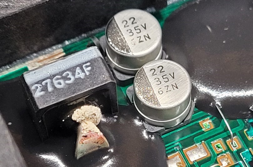
The #1 one issue with these boards is the electrolytic capacitors 95% of the time, they’re the culprit. They tend to leak and eventually dry out, with the electrolyte seeping out from the bottom. I’ll include photos showing examples of dried-up electrolytic residue to highlight the problem.
Leakage Under Main Filter Caps (Minor Leakage Here)
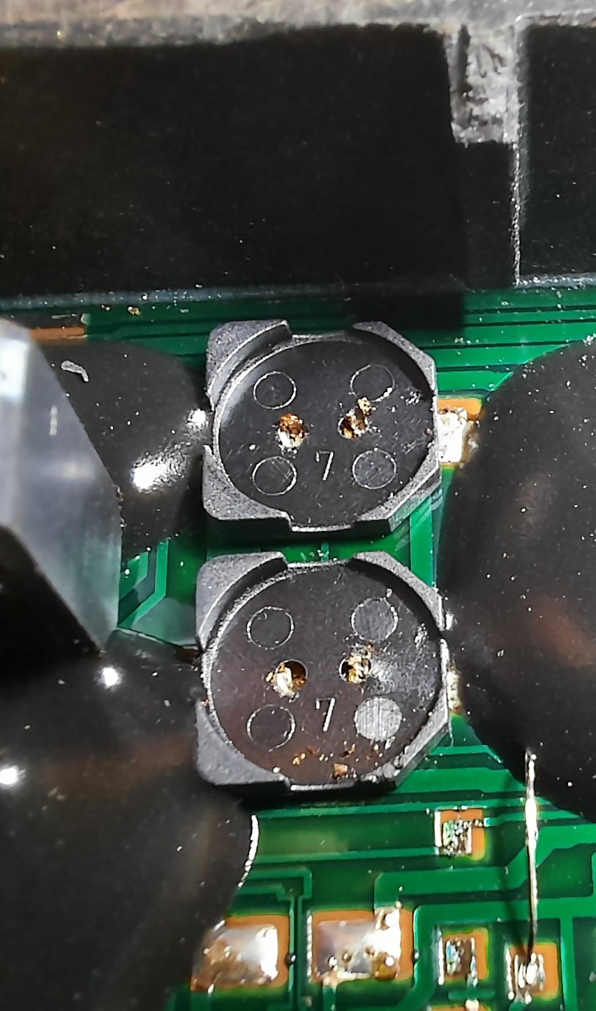
Leakage Under Switching Caps (Moderate Leakage on Right Cap)
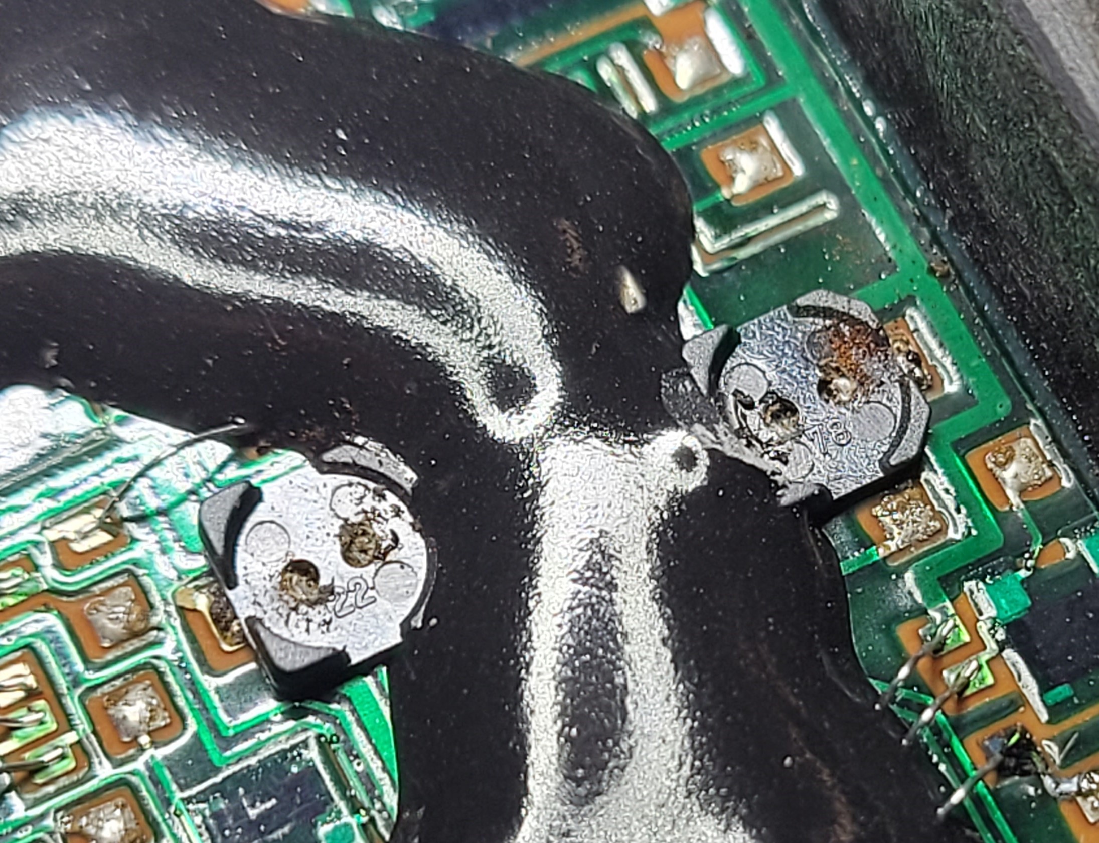
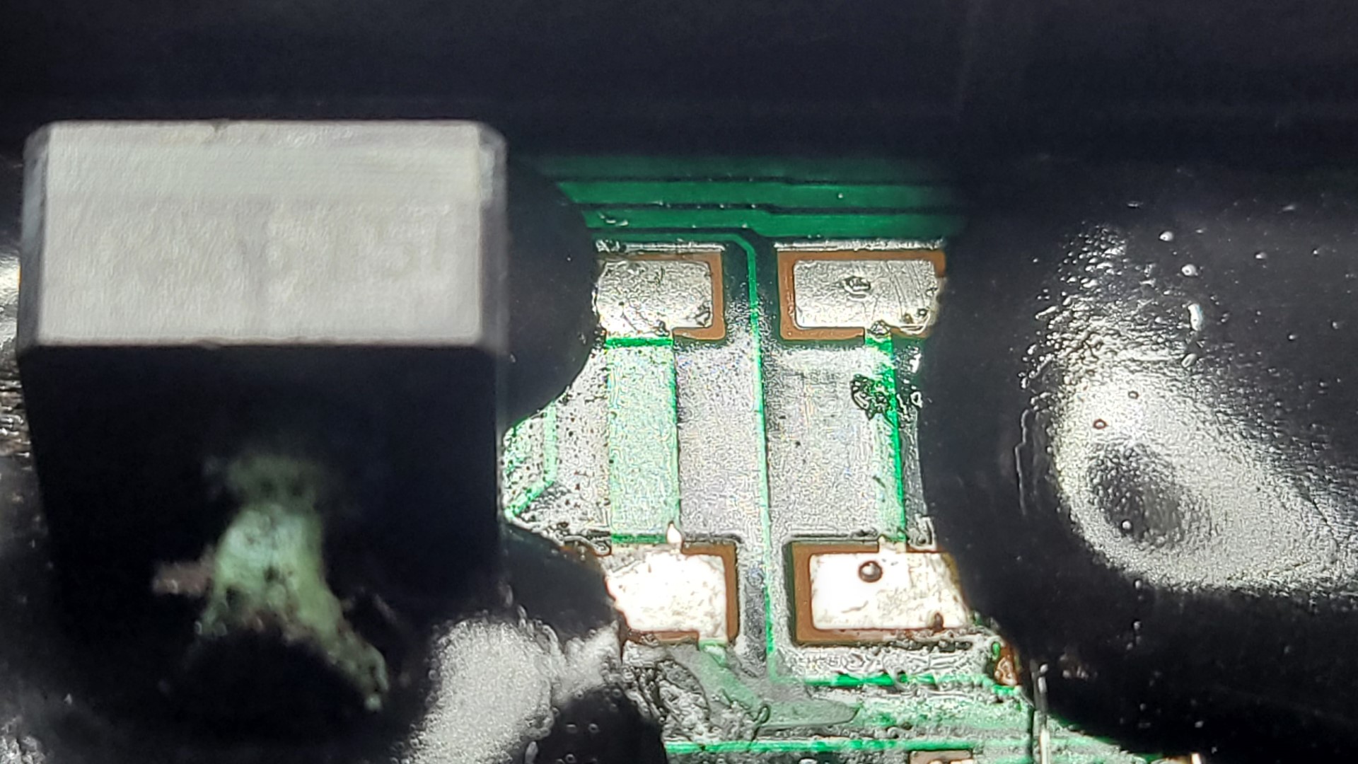
#2 Issue: The second most common problem originates from the electrolytic capacitors. When the electrolyte leaks, the acid corrodes and destroys the conductive adhesive on the bonding wires. Although the wires may look attached, the adhesive often softens or corrodes, resulting in broken or high-resistance connections. In many cases, the bonding wire appears to be stuck to the pads but is actually held in place by corrosion, with no real continuity. A good microscope is used to inspect each bonding wire connection.
The bonding wires themselves are made of a soft aluminum alloy, which is challenging to work with since solder doesn’t adhere to it. This makes repairs even more delicate and requires careful handling to restore proper functionality.
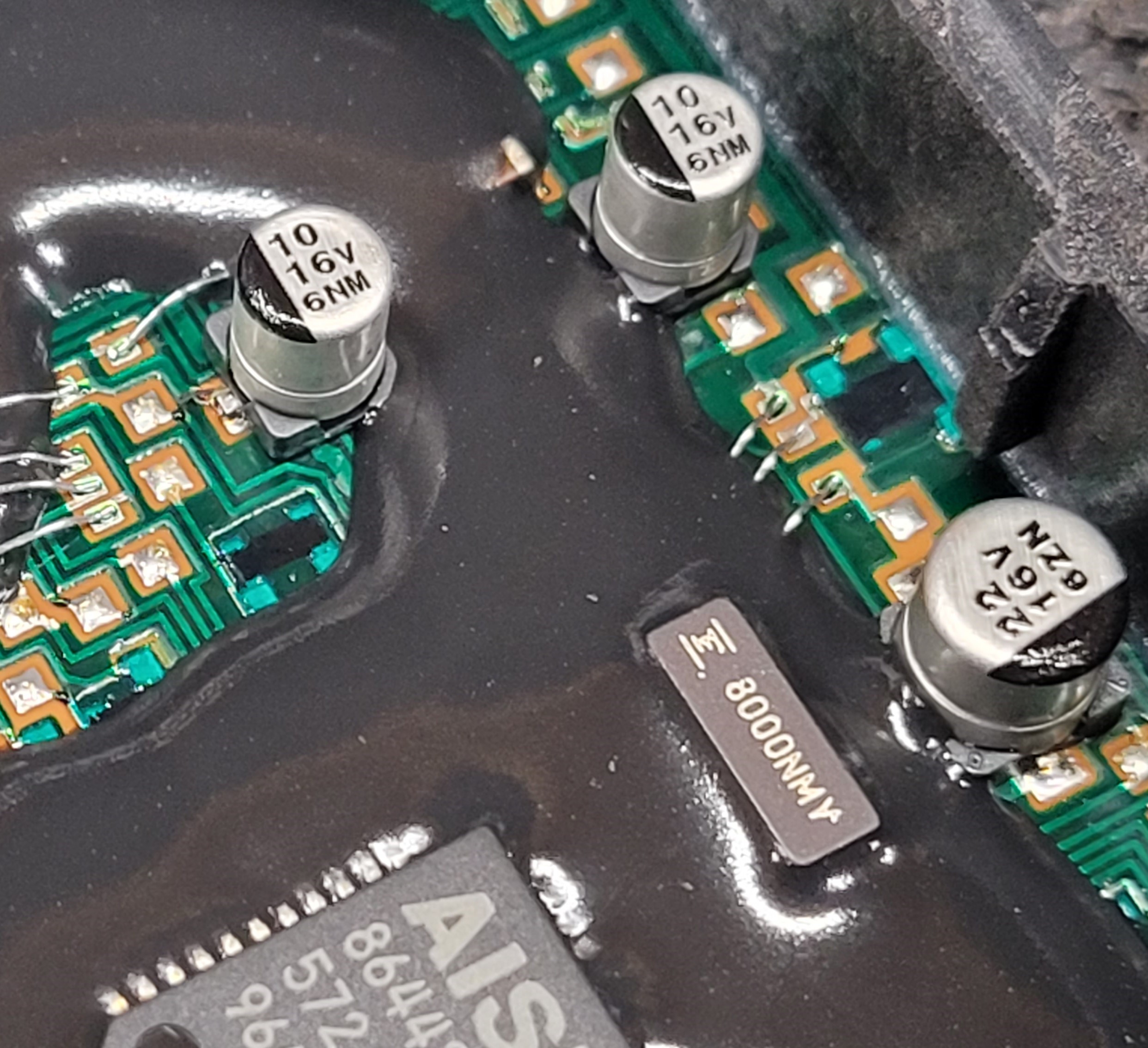
Most Common spot, for this to happen is between 2 Capacitors at the end of the board. (But can and does happen other area’s)
With the connector facing you there are 2 caps 22uf and 10uf at the top and 3 Small Bonding Wires that go in to the epoxy.

Another Angle
1st Bonding Wire is Ground for half the board this can be connected to the GND Pad of the 22uf Cap.
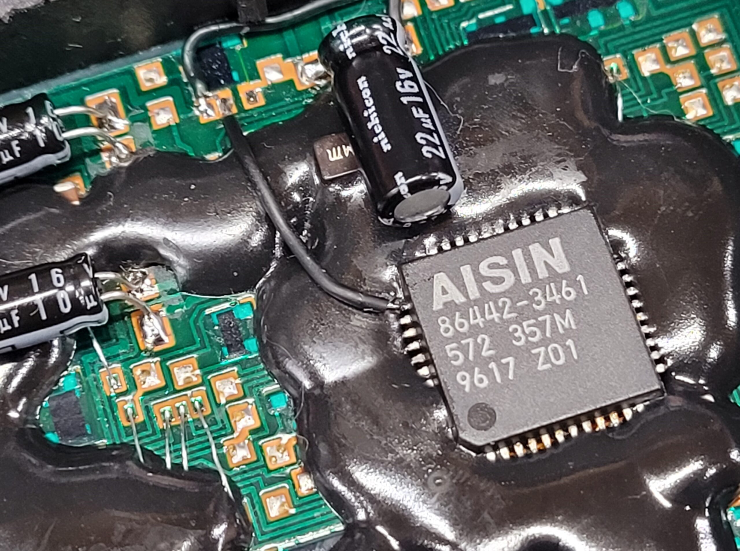
2nd Bonding Wire: This bonding wire connects to a pad linked to a carbon-printed resistor buried deep within the epoxy. Fortunately, there’s an alternate connection point on the MCU, likely pin 38 or 39 (see attached photo). You can confirm this by checking continuity to the small piece of wire still embedded in the epoxy.
Sometimes this MCU pin is exposed, while other times, it’s covered in epoxy. However, it’s the most accessible spot to attach with minimal epoxy removal, making it a practical solution for repairs.
3rd bonding wire: No Connection.
#3 is Corrosion and micro cracks at the printed carbon resistors making an open circuit. There are Nearly impossible to repair if the printed resistors are covered in epoxy without lots of grinding away at the epoxy. See Photo above the black squares are printed carbon resistor there are many of them on the PCB.
#4 Zener Diode This Photo Marked 27634F. If Open / Shorted will replace with equivalent generally a U5ZA27C.
#5 Less Common Issue: Occasionally, the TCU will have a burnt component buried under the epoxy, rendering it beyond repair “for now ” I’ve encountered this in three cases, typically caused by a short on the input TPS 12-pin connector (Pin 6, Green/White Wire) or the Engine 16-pin connector (Pin 3, Pink Wire).
I used to replace thee capacitors with SMD parts, but the time and effort required to grind away epoxy for proper connections made the process too costly. To save time (at least an hour) and reduce the risk of damaging the PCB, I switched to using leaded radial capacitors.
Important Reminder: Always clean the pads thoroughly before installing new components. Remove the old, contaminated solder, capacitor leads, and neutralize the electrolyte. In some cases, you may need to grind away epoxy to free the plastic base of the old capacitor, as they’re glued down. A little heat can help loosen the adhesive, making removal much easier.
I plan to share all the alternate connection points and measurements for the printed carbon resistors on my blog. Additionally, I’ll use a surface grinder or fiber laser to carefully remove the epoxy layer from one of the scrap boards to uncover the components beneath. I might even go a step further and create a reproduction board, allowing units that are currently beyond economical repair to be salvaged by swapping the MCU.
Last Updated on March 30, 2025 by Steven Rhine