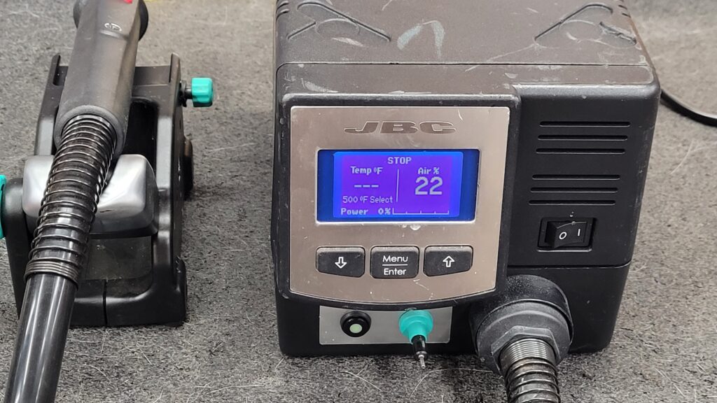
I Ran across this JBC JTE-1A C.UNIT JT-TE Hot-Air Rework Station form a Local I just had to Snag it as I want to see what inside. This is what I found Out.
JBC JTE-1A JT-TE Hot Air Rework Station Appears to have Low Hours

JBC JTE-1A C.UNIT JT-TE Hot-Air Rework Station Firmware Version 9996786

Says Made in EU, I am Seriously Doubting that The JBC Tools are Made in the EU or ther Major Components are they Look Like made in China from the Workmanship. If These are Made By JBC they really need pay attention to details. Keep Reading. If The JBC stations are actually made in the EU Not just assembled there I challenge JBC to show a tour of the production facilities.

I already Removed the Cover Just for an Inspection.

At the price of these things one would want absolute perfection not Bodges seems like a running theme with JBC.

Larger Photo of the JBC JTE-1A JT-TE Hot-Air Rework Station Main Board Top Circuit 0005430
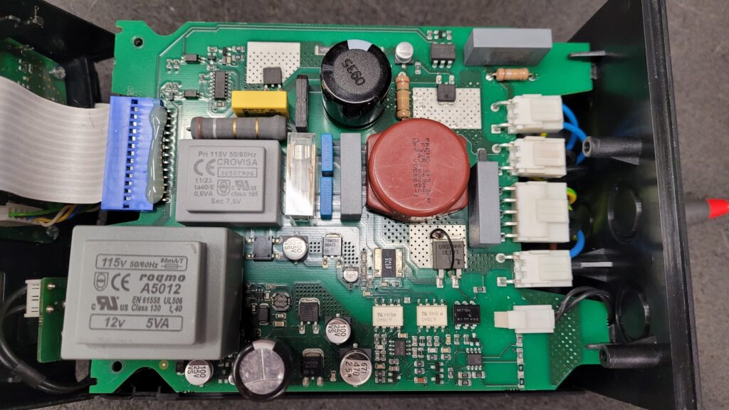
Back Side of the JBC JTE-1A JT-TE Hot-Air Rework Station Main Board Top Circuit.

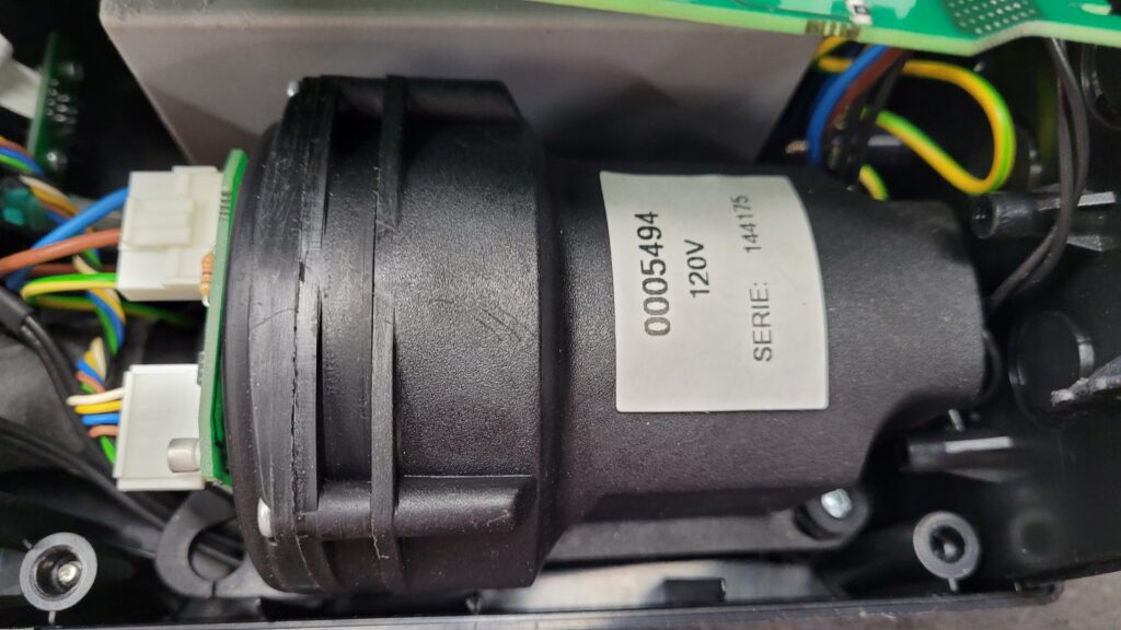
Moster JBC JTE-1A JT-TE Hot-Air Rework Station Air Pump 0005494
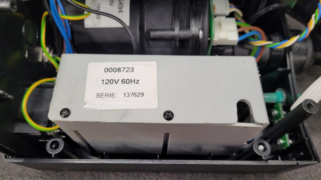
Suction Pump 0008723 For JBC JTE-1A JT-TE Hot-Air Rework Station Vacuum System (I replaced the Screws With Some that Grip a Little Better)
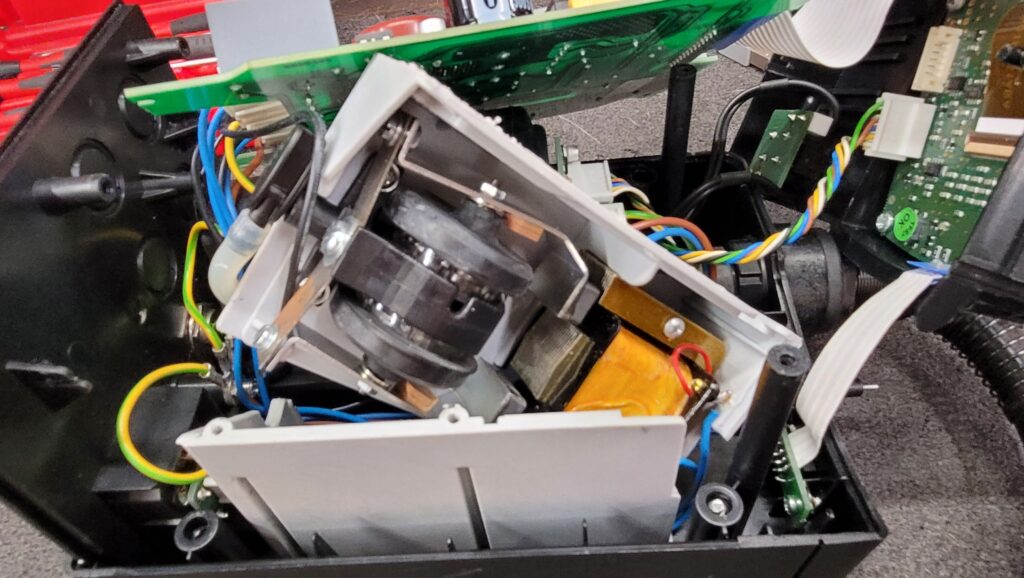
Close look at the JBC JTE-1A JT-TE Hot-Air Rework Station Vacuum System Internals (Reminds Me of an Aquarium Pump) the ones that the diaphragms always seem to go bad in I wonder if JBC Tools sell the Diaphragms?
There is a Manufacture “Claber Italy” Printed on the Pneumatic Line Connector. Claber Italy Makes Irrigation Equipment Sprinklers and Valves?

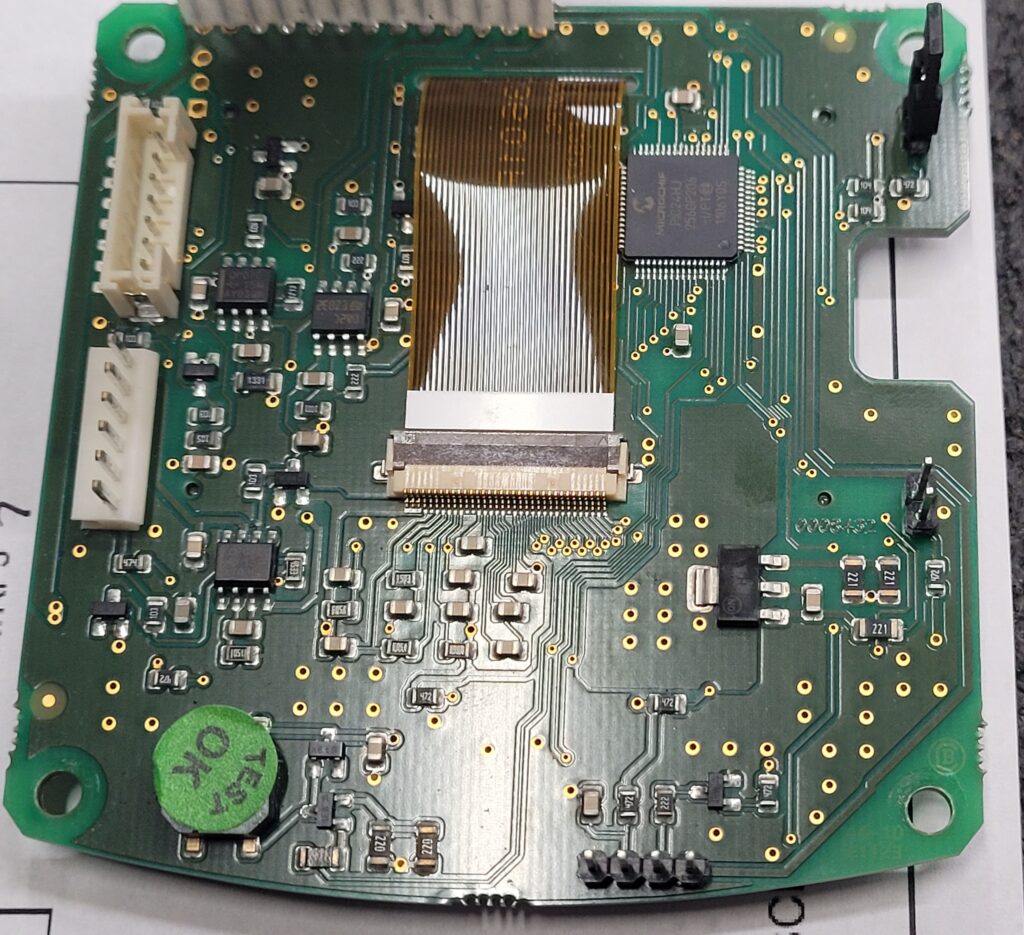
Front Circuit 0008442 Display/CPU/MPU Board JBC JTE-1A JT-TE Hot-Air Rework Station (I Will Explore this Board a Little Later)
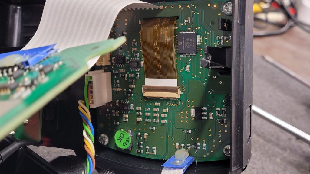
LCD Side Look at all that flux Residue JBC Really Can you Not Clean Up Your Flux this Screams Made in China!! Similar Flux Mess and Poor Incomplete Solder Connections on the JBC Tools Seen On the MSE-A Teardown
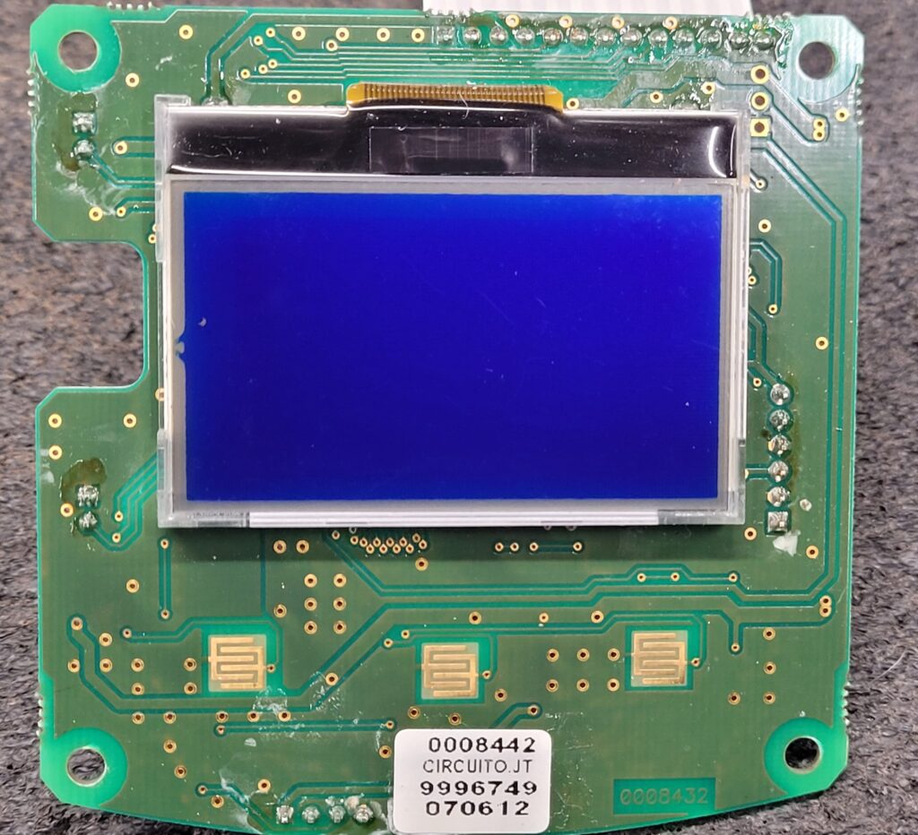
JBC Tools Fine Attention to detail’s More Incomplete Soldering of the Ribbon Cables. I Sure Hope if this was Made in the EU at JBC Facilities was not assembled with JBC Soldering Irons.

JBC JTE-1A JT-TE Hot-Air Rework Station Display CPU Board MCU PIC24HJ256GP206 TQFP64 Data Sheet
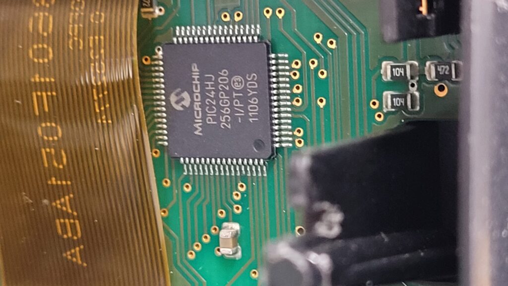
JBC JTE-1A JT-TE Hot-Air Rework Station Display CPU MCU Board Unknown 7 Pin Connector (JST PH 2.0?) Possibly An In system Programming Header That would be My Guess.
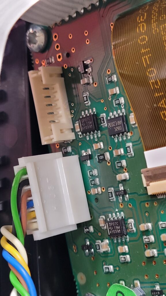
There are a few Devices I can use to attack this Target if that is the In system Programming Header Let see which one will be the best for this situation.

First I Looked up the PIC24HJ256GP206 Micro-controller in My Xeltek IS01 In system Programmer and it is Listed With 7 Connections. So I will Assume this connector is for In circuit Programming. At a later date I will Probe it out and publish the pinouts. I will also ask JBC but they will prob say it is a trade secrete proprietary and confidential. I think companies forget what a trade secret is. As for confidential it will not be hard to use my eyes the datasheet and a meter to locate where that header goes and to what pins. I will attempt to backup the firmware just in case I ever need it. 50% of manufacture read protect the devices so always worth a shot to give it an attempt.
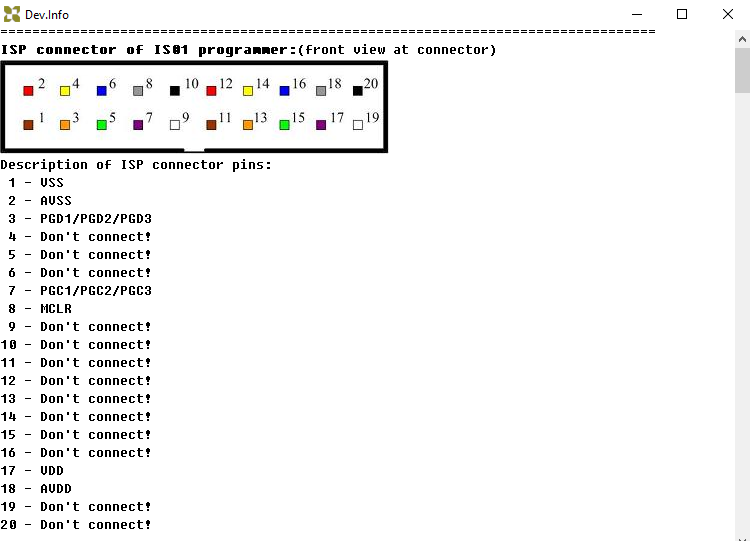
If Using the Xeltek IS01 on the PIC24HJ256GP206 Will Pull the Pinouts form the Datasheet

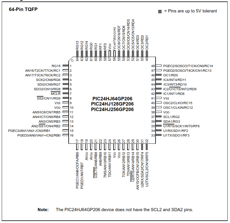
There is also a Jtag Port. But do not think that they are using that for in sysem programming.
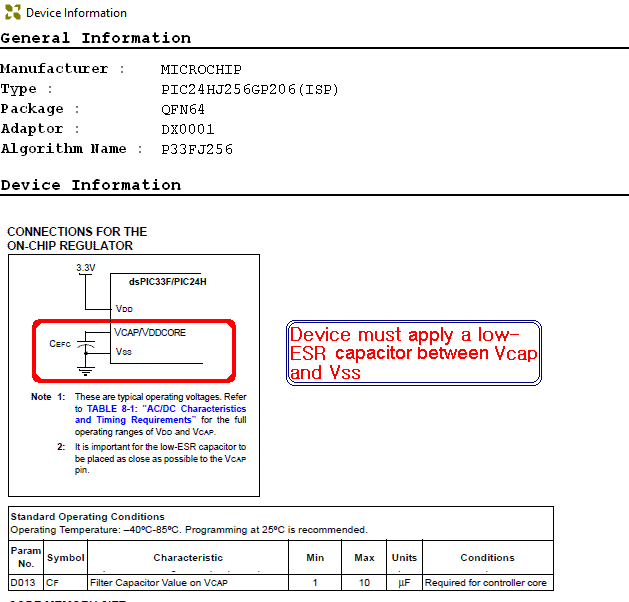
This MCU Is also Supported on the Xeltk 6100N for In System Programming but is a 5 pin interface and not sure if the cap is on the main board. so prob using the ISP configuration above.

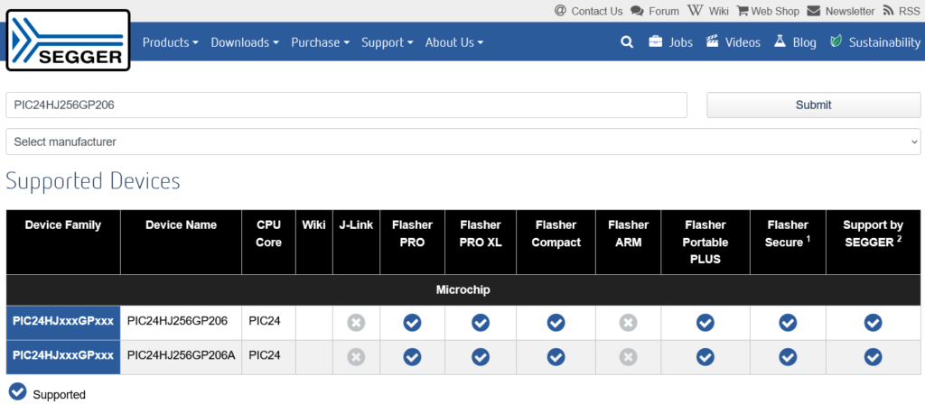
This I Searched Segger Site and the PIC24HJ256GP206 is also Supported with the Segger FLasher Pro and the Segger Flasher Portable Plus I Have Both.

Connections on the Segger Flasher pro to Target Device.
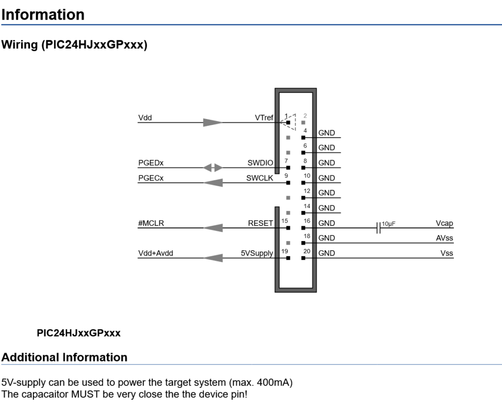
June 29th 2024
I sent an E-mail requesting the Pinout and firmware so I could have a back up copy as we all know things break. My e-mail to jbc and text messages to my Local rep went unanswered yet again i guess not even a new LOL. So I took the time to trace out the connections. They are as Follows
Assuming Pin 1 Is Top | Target Device
Pin 1 = MCLR | Pin 7
Pin 2 = VDD/AVDD | Pin 19
Pin 3= VSS /AVSS | Pin 20
Pin 4 = PGED2 | Pin 47
Pin 5 = PGEC2 | Pin 48
Pin 6 = U1RX | Pin 34
Pin 7 = U1TX | Pin 33
![]()
Odd they are Using the the UART Pins Here I will Hook it up and See if I can Get a read Out in a Terminal.
Pin Map

Last Updated on June 30, 2024 by Steven Rhine
[…] for the Brains a bit Overkill for being a Desolder Controller. It is the Same MCU in the JTE-1A JT-TE Hot-Air Rework Station I did a tear down of last weekend. I will Assume that this is a AVX Stype Debug / In Systeem […]